Writing Your First Boot Sector
Before we begin
Section titled “Before we begin”This lesson assumes that you have no previous system-programming or assembly knowledge. If you can open a terminal and edit a text file, you already have everything you need.
Most programming happens comfortably on top of an operating system, which quietly handles the messy details of hardware for you. Here, we are going underneath all of that - to the handful of ideas an operating system itself is built from. It is a different kind of programming: slower to start, closer to the metal, and - once the first message appears on screen - surprisingly satisfying.
We will start with the physical pieces inside a PC and work, one small idea at a time, toward a program that starts up with no Windows, no Linux, and no operating system of any kind underneath it - just the CPU, memory, and a handful of instructions you wrote yourself.
By the end, you will understand:
- The different jobs of the CPU, memory, storage, firmware, and peripherals.
- How a CPU sees instructions, data, memory addresses, and registers.
- Why assembly source code must be translated into machine code.
- How the stack, labels, loops, and subroutines work.
- How the BIOS finds and starts a 512-byte boot sector.
You will also produce:
| Artifact | Size | Purpose |
|---|---|---|
boot.bin |
512 bytes | Bootable machine code and the BIOS boot signature |
lesson-00.img |
1,474,560 bytes | A floppy-disk image containing boot.bin |
| Screen output | One line | Peace be upon you! |
1. The main parts of a PC
Section titled “1. The main parts of a PC”An application normally sits on top of an operating system. The operating system handles the hardware, so the application rarely needs to know how the machine starts or how a character reaches the screen.
We are going below that layer, down to the five parts that make it all possible:
The central processing unit, or CPU, executes instructions - and only instructions. It doesn’t understand your code’s intent, only bytes whose bit patterns tell it to copy a number, compare two values, read a byte from memory, or jump to another part of a program.
Left to itself, the CPU just repeats one simple cycle, forever:
- Fetch the next instruction from memory.
- Decode what the instruction means.
- Execute it.
- Continue with the next instruction, unless the current instruction says to jump.
Everything a computer ever does - a boot sector printing one line, or an operating system running a thousand programs at once - is this same four-step cycle, running billions of times per second. The CPU can execute only machine code: bytes whose bit patterns represent instructions. It cannot directly execute a NASM source file, no matter how carefully you write it.
Memory (RAM)
Section titled “Memory (RAM)”RAM is the machine’s temporary working area - closer to a desk you spread papers out on than a place you store them long-term. Programs must be copied into RAM before the CPU can execute them, and everything on that desk is cleared the moment power is removed.
Memory is a long sequence of numbered byte-sized locations. The number of a
location is its address. If a byte is stored at address 0x7C00, the CPU
can use that address to find it again - the same way a house number lets a
letter carrier find one specific house on a very long street.
Storage
Section titled “Storage”A floppy disk, hard disk, or solid-state drive provides persistent storage - the filing cabinet to RAM’s desk. Its contents remain after the machine is turned off, which is exactly why our program has to start there before it can run anywhere.
Storage and RAM are not interchangeable:
| Storage | RAM |
|---|---|
| Keeps files and disk sectors persistently | Holds the program and data currently in use |
| Read through a storage controller or firmware service | Read directly by the CPU |
| Usually much larger but slower | Usually smaller but faster |
At startup, our code is on storage. Before it can run, something must copy it into RAM - and figuring out what that “something” is turns out to be the whole point of this lesson.
Firmware (BIOS)
Section titled “Firmware (BIOS)”The BIOS is firmware supplied with a traditional PC - the first thing awake in the building, so to speak. It is the first software that runs after power-on: it initializes hardware, chooses a boot device, and loads the first piece of our program into that desk we just described.
The BIOS also provides small routines for tasks such as reading a disk sector or printing a character - conveniences it’s happy to lend out before anything else exists to do the job. Our first program will ask one of those routines to display text on our behalf.
Peripherals
Section titled “Peripherals”The display, keyboard, disk drive, and similar devices are peripherals. The CPU never touches them directly; it always goes through a controller built for that specific piece of hardware. In this lesson we let the BIOS deal with the display controller so we don’t have to yet.
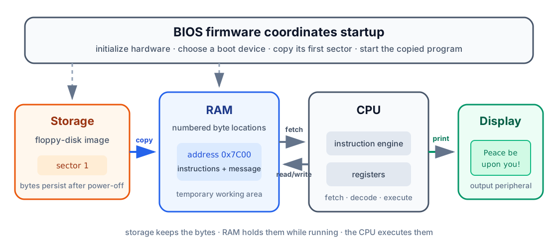
The important path, the one this whole lesson is really about, is:
disk storage → BIOS copies bytes → RAM → CPU executes bytes → screen output2. Bits, bytes, and hexadecimal
Section titled “2. Bits, bytes, and hexadecimal”Computers store information with two states, written as 0 and 1. One such
state is a bit. Eight bits make one byte.
A byte can hold 256 different bit patterns, from 00000000 through
11111111. Writing long binary values by hand gets tedious and error-prone
fast, so system programmers commonly use hexadecimal, a base-16 number
system that packs the same information into far fewer digits.
Hexadecimal uses the digits 0-9 followed by A-F:
| Decimal | Hexadecimal | Binary |
|---|---|---|
| 0 | 0x00 |
00000000 |
| 10 | 0x0A |
00001010 |
| 15 | 0x0F |
00001111 |
| 16 | 0x10 |
00010000 |
| 255 | 0xFF |
11111111 |
The prefix 0x tells the reader that a number is hexadecimal. NASM also
accepts an h suffix, but this tutorial consistently uses the 0x form.
Two terms appear frequently in x86 documentation, and you’ll see them constantly from here on:
- A byte is 8 bits.
- A word is 16 bits, or 2 bytes.
Hexadecimal does not change the stored value, only how it looks on the page.
255, 0xFF, and 11111111 are three different spellings of the exact same
number - pick whichever is easiest to read in context.
3. Memory and addresses
Section titled “3. Memory and addresses”Imagine RAM as a very long row of numbered boxes, side by side, each one holding exactly one byte:
Address 0x7C00 0x7C01 0x7C02 0x7C03 ...Stored byte FA B8 C0 07 ...The addresses identify where the bytes are. The values in the boxes are the actual instructions or data - the address tells you nothing about what’s inside the box until you know how the program intends to use it.
The same bytes can mean entirely different things depending on how a program uses them:
- A CPU instruction.
- A number.
- A letter encoded as text.
- Part of a memory address.
For example, the letter A is represented by the value 0x41 in ASCII, a
common text encoding. Our message will be stored as a sequence of such byte
values followed by a zero byte - a detail that matters a great deal once we
get to Step 3 below.
The address of our boot sector
Section titled “The address of our boot sector”The BIOS copies the first disk sector to memory beginning at physical address
0x7C00. If our sector contains 512 bytes, they occupy addresses 0x7C00
through 0x7DFF - a fixed, well-known spot the BIOS has used for this purpose
since the earliest PCs.
The CPU needs a reliable way to refer to code and data in that region. Early x86 addressing uses a segment and an offset:
physical address = segment × 16 + offsetFor our program:
0x07C0 × 0x10 + 0x0000 = 0x7C00You do not need to explore every x86 addressing scheme yet - that story
continues in Lesson 02. For now,
remember only that we will use segment 0x07C0 as the base of the loaded boot
sector, and labels inside it will be offsets measured from that base.
4. Registers: the CPU’s immediate workspace
Section titled “4. Registers: the CPU’s immediate workspace”Reading RAM is fast, but the CPU keeps an even smaller workspace right inside itself: registers. If RAM is the desk, registers are more like the CPU’s own two hands - the handful of values it can act on instantly, without reaching anywhere else.
Unlike variables in a high-level language, x86 registers have fixed names and special conventional uses that you’ll simply come to recognize with practice.
The 8086 register file
Section titled “The 8086 register file”The 8086 actually offers more registers than any single program is likely to need. Seeing the whole family at once - general-purpose, pointer/index, segment, and special-purpose - makes it easier to place the few we actually use in their proper context, instead of meeting them as an unexplained list of two-letter names.

This lesson only touches a handful of these - the highlighted ones above. The
rest, like CX/DX for counting and DI/BP for more advanced addressing,
will earn their place in later lessons. There’s no need to memorize the full
table now; just know it’s there so nothing you meet later feels unfamiliar.
Registers used in this lesson
Section titled “Registers used in this lesson”| Register | Role in our program |
|---|---|
AX |
General working register and BIOS function selection |
AH / AL |
Upper and lower 8-bit halves of AX |
BX |
Supplies display page and color values to the BIOS |
SI |
Holds the offset of the next message character |
DS |
Holds the base segment for our data |
ES |
A second data segment, initialized now for predictable later use |
SS |
Holds the base segment of the stack |
SP |
Holds the offset of the top of the stack |
IP |
Points to the next instruction; the CPU updates it automatically |
AX is a 16-bit register, but its two halves can also be addressed
separately, like a drawer you can open all the way or open just the front
half of:
AX┌───────────────┬───────────────┐│ AH: high byte │ AL: low byte │└───────────────┴───────────────┘This is why one BIOS call can use AH to select an operation while using AL
for the character involved in that same operation - two independent pieces of
information riding in one register.
Segment:offset pairs
Section titled “Segment:offset pairs”Section 3 introduced the formula physical address = segment × 16 + offset,
but glossed over one detail: which registers actually supply those two
halves. The answer is that a segment register never works alone - each one is
conventionally paired with a specific offset register, and together the pair
names one exact byte in RAM:
| Pair | Points at |
|---|---|
CS:IP |
The next instruction the CPU is about to fetch |
DS:SI |
The next byte of the message we are printing |
SS:SP |
The current top of the stack |
You never set CS:IP directly - the CPU updates it automatically as
instructions run, and CALL, JMP, and RET are the only ways to redirect
it. DS and SS, on the other hand, are ours to initialize explicitly, which
is exactly what Step 2 in Section 8 does before the program touches any data
or the stack.
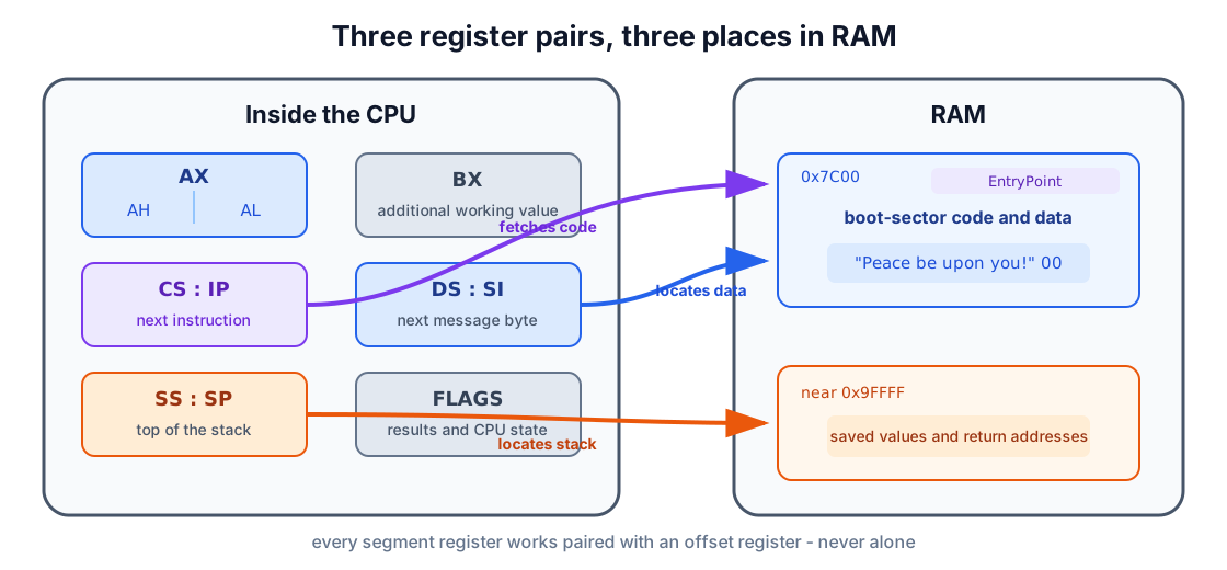
The CPU also maintains individual state bits called flags, a kind of
running scoreboard of “what just happened.” An instruction such as TEST
updates flags to describe its result. A following instruction such as JZ can
then jump based on that scoreboard - here, specifically, when the result was
zero.
Our loop uses this pair to detect the zero byte at the end of the message, which is how the program knows when to stop printing.
The stack
Section titled “The stack”The stack is an area of RAM used in last-in, first-out order - picture a stack of plates: the last one you set down is the first one you pick back up.
push AX → save AX on top of the stackpush BX → save BX above itpop BX → restore the most recently saved valuepop AX → restore the value saved before thatSS and SP locate the top of that stack of plates, and it grows toward
lower addresses as things get pushed onto it. It’s used for temporary values
and for return addresses whenever one part of a program calls another.
5. From assembly source to machine code
Section titled “5. From assembly source to machine code”Machine code is difficult for humans to read and write directly - it’s just raw bytes. Assembly language exists to give those bytes names a human can actually hold in their head.
For example:
mov ax, 0x07C0This asks the CPU to copy the value 0x07C0 into register AX.
An assembler translates each readable instruction into the machine code bytes it stands for. We use NASM:
boot.s ──NASM──> boot.binsource text machine-code bytesAssembly source contains several kinds of line, and it helps to be able to name each one on sight:
| Kind | Example | Meaning |
|---|---|---|
| Instruction | mov ds, ax |
An operation the CPU will execute |
| Label | ShowMsg: |
A name for a location in the program |
| Directive | [BITS 16] |
Information for NASM, not a CPU instruction |
| Data definition | db "Hello", 0 |
Bytes to include in the output file |
| Comment | ; initialize the stack |
Explanation ignored by NASM |
A few instructions before we use them
Section titled “A few instructions before we use them”| Instruction | Plain-language meaning |
|---|---|
mov destination, source |
Copy a value |
call label |
Run a subroutine and remember where to return |
ret |
Return to the instruction after call |
jmp label |
Continue at another label |
push register |
Save a register value on the stack |
pop register |
Restore a value from the stack |
int number |
Request a software service; here, a BIOS routine |
hlt |
Stop executing instructions until the CPU is awakened |
6. How the BIOS starts our program
Section titled “6. How the BIOS starts our program”After the PC is powered on, the BIOS:
- Initializes enough hardware to begin booting.
- Chooses a boot device.
- Reads that device’s first 512-byte sector into memory at
0x7C00. - Checks for a recognizable signature in the final two bytes.
- Tells the CPU to begin executing the copied instructions.
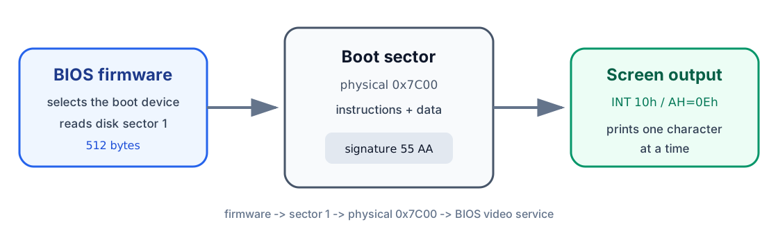
That first sector is called the boot sector, and it lives by different rules than the programs you may be used to: there is no operating system to load it, no executable header, and no runtime library standing behind it. The sector contains nothing but the bytes the BIOS and CPU actually need - not one more.
The BIOS also leaves the number of the selected boot drive in register DL.
We will save and use it in Lesson 01.
This first program does not read more data from disk, so it does not need
that number yet - but it’s worth remembering it’s already sitting there,
waiting.
7. Anatomy of a boot sector
Section titled “7. Anatomy of a boot sector”A BIOS boot sector is exactly 512 bytes - not one byte more, as we’ll see later, and the BIOS is strict about this.
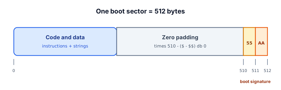
| Region | Contents |
|---|---|
Bytes 0-509 |
Instructions, strings, and padding |
Byte 510 |
Signature byte 0x55 |
Byte 511 |
Signature byte 0xAA |
NASM writes the signature with:
dw 0xAA55DW means define word, so NASM emits a 2-byte value. x86 stores the lower
byte first, which turns the word 0xAA55 into the disk bytes 55 AA - the
exact pattern the BIOS scans for before it trusts a sector enough to run it.
The instruction below inserts exactly enough zero bytes to place the signature at offset 510, however much code comes before it:
times 510 - ($ - $$) db 0The symbols have special meanings to NASM:
$is the current position.$$is the beginning of the current section.$ - $$is therefore the number of bytes emitted so far.DB 0means emit one zero byte.
If the program grows beyond the available 510 bytes, NASM reports an error instead of silently creating an invalid sector - a small mercy, since a silently truncated boot sector would be a much harder bug to track down.
8. Building the program one idea at a time
Section titled “8. Building the program one idea at a time”We now have every piece we need. Let’s build the program without treating a single line as magic.
Step 1: tell NASM what we are producing
Section titled “Step 1: tell NASM what we are producing”[BITS 16][ORG 0]BITS 16 tells NASM which instruction encoding the CPU expects at startup.
ORG 0 tells NASM to calculate labels as offsets beginning at zero. We will
place 0x07C0 in DS, so DS supplies the base address 0x7C00 and each
label supplies an offset within the loaded sector.
Step 2: initialize the data registers and stack
Section titled “Step 2: initialize the data registers and stack”The BIOS handed control to our code, but it makes no promises about what the data and stack registers happen to contain at that moment - so the first job is to stop assuming and start setting things explicitly.
EntryPoint:    cli
    mov ax, 0x07C0    mov ds, ax    mov es, ax
    mov ax, 0x9000    mov ss, ax    mov sp, 0xFFFF
    cld    sti
Line by line:
| Code | Meaning |
|---|---|
cli |
Temporarily prevent ordinary hardware events from interrupting stack setup |
mov ax, 0x07C0 |
Put the boot-sector base segment in a general register |
mov ds, ax |
Make data labels refer to the loaded boot sector |
mov es, ax |
Initialize the second data segment to the same base |
mov ax, 0x9000 |
Choose a separate region for the stack |
mov ss, ax |
Set the stack’s base segment |
mov sp, 0xFFFF |
Set its starting top offset |
cld |
Make string-reading instructions advance toward higher addresses |
sti |
Allow maskable hardware interrupts again |
x86 does not allow a constant to be copied directly into a segment register,
so the value has to travel through AX first: mov ax, 0x07C0, then
mov ds, ax. It’s an extra line, but not an optional one.
The CLI/STI pair is safe initialization boilerplate for now - it creates a
short quiet period while the stack changes, so nothing can interrupt us
mid-setup. Interrupt handling in general gets its own lesson later; for now,
treat this pair as a seatbelt you buckle without needing to know how the car
works.
Step 3: store the message
Section titled “Step 3: store the message”bootMsg db "Peace be upon you!", 13, 10, 0DB means define bytes. NASM converts the quoted characters to their
text byte values, then appends:
13: carriage return, moving the cursor to the start of the line.10: line feed, moving the cursor down one line.0: a terminator that marks the end of the string.
The zero is never displayed. It’s purely an end marker, a signpost our loop will learn to recognize in Step 5.
Step 4: point to the first character
Section titled “Step 4: point to the first character”mov si, bootMsgcall ShowMsgbootMsg is a label. NASM quietly replaces it with the offset where those
message bytes actually ended up - you never have to compute that address by
hand.
Together, DS:SI identifies the next message byte:
DSsupplies the boot sector’s base.SIsupplies the offset of the current character.
CALL begins the ShowMsg subroutine. It also saves a return address on the
stack behind the scenes, which is exactly what lets RET find its way back to
resume at the instruction after the call.
Step 5: read the message one byte at a time
Section titled “Step 5: read the message one byte at a time”Assembly has no built-in string object that remembers its own length - that
convenience simply doesn’t exist yet at this level. Our “string” is nothing
more than a sequence of character bytes sitting next to one another in
memory, and bootMsg names the address of the very first one.
Here is a shorter example to see the shape clearly:
message db "Hi", 0NASM stores it as:
Offset from message |
Stored byte | Meaning |
|---|---|---|
0 |
0x48 |
H |
1 |
0x69 |
i |
2 |
0x00 |
End of the string |
This convention is called a null-terminated string. “Null” means the zero
byte 0x00. It is never displayed as a character; it exists purely to tell
the reading loop where to stop. Without that final zero, the loop would keep
marching forward into whatever bytes happen to sit next in memory - almost
certainly not text, and almost certainly not what you want on screen.
Our complete message works the same way:
bootMsg db "Peace be upon you!", 13, 10, 0It contains the text bytes, the carriage-return and line-feed bytes, and finally the zero terminator that closes it off.
ShowMsg:    push ax    push bx    push si
.loop:    lodsb    test al, al    jz .done
    mov ah, 0x0E    mov bx, 0x0007    int 0x10    jmp .loop
.done:    pop si    pop bx    pop ax    ret
The routine first saves the registers it is about to change, then restores them in reverse order right before returning - good manners for any subroutine that borrows registers it doesn’t own.
On each pass, LODSB places the next byte in AL. TEST AL, AL compares
that value against itself; the result can only be zero when AL itself is
zero, and the CPU records that in its zero flag. If AL holds the null
terminator, JZ .done reads that flag, takes the jump, and the routine is
done. Otherwise, the byte is an ordinary character and the BIOS displays it.
The loop works like this:
| Instruction | Effect |
|---|---|
lodsb |
Load the byte at DS:SI into AL, then advance SI |
test al, al |
Check whether that byte is zero |
jz .done |
Leave the loop when the terminator is reached |
mov ah, 0x0E |
Select the BIOS teletype-output service |
mov bx, 0x0007 |
Select display page 0 and a standard text color |
int 0x10 |
Ask the BIOS to display the character in AL |
jmp .loop |
Repeat for the next byte |
The BIOS call itself works like a tiny paper request form, filled out one register at a time:
| Register | Request field |
|---|---|
AH = 0x0E |
Operation: print one character |
AL |
Character to print |
BH = 0 |
Display page |
BL = 7 |
Foreground color when relevant |
Step 6: stop after returning
Section titled “Step 6: stop after returning”.hang: cli hlt jmp .hangThere is no operating system to return control to, and no next application waiting to launch - once our message is printed, there is genuinely nothing left to do. The program disables ordinary hardware interrupts and halts, and the backward jump makes sure that even if the CPU is ever woken back up, it loops right back into this same quiet stop instead of wandering off into whatever padding bytes come next.
9. Complete boot-sector source
Section titled “9. Complete boot-sector source”The ideas above form the complete lesson 00/src/boot.s program - every line
below should now read as something you’ve already met, not something new.
; AOS Lesson 00 - Writing your first boot sector
[BITS 16][ORG 0]
EntryPoint:    ; Establish known data segments and a safe stack.    cli
    mov ax, 0x07C0    mov ds, ax    mov es, ax
    mov ax, 0x9000    mov ss, ax    mov sp, 0xFFFF
    cld    sti
    mov si, bootMsg    call ShowMsg
.hang:    cli    hlt    jmp .hang
; Print the zero-terminated string at DS:SI with BIOS teletype output.ShowMsg:    push ax    push bx    push si
.loop:    lodsb    test al, al    jz .done
    mov ah, 0x0E    mov bx, 0x0007    int 0x10    jmp .loop
.done:    pop si    pop bx    pop ax    ret
bootMsg db "Peace be upon you!", 13, 10, 0
times 510 - ($ - $$) db 0dw 0xAA55
The same source is available in the repository: lesson 00/src/boot.s.
Trace the whole execution
Section titled “Trace the whole execution”Before assembling it, it’s worth walking the program once, start to finish, purely in your head:
- The BIOS copies the sector from disk to memory at
0x7C00. - The CPU begins at
EntryPoint. - The program initializes its data registers and stack.
SIreceives the offset ofbootMsg.CALLsaves a return address and entersShowMsg.LODSBreads one character intoAL.- If the character is not zero,
INT 10hdisplays it. - The loop repeats until the zero terminator is found.
RETuses the saved return address to leaveShowMsg.- The program enters its halt loop.
If that trace makes sense end to end, you already understand this program better than the syntax alone would suggest.
10. Assemble and inspect the sector
Section titled “10. Assemble and inspect the sector”NASM’s bin output format writes the assembled bytes directly, with no
application header or extra metadata wrapped around them - what you see is
genuinely everything that ends up on disk.
mkdir -p "lesson 00/build"nasm -f bin "lesson 00/src/boot.s" -o "lesson 00/build/boot.bin"The quotation marks are necessary because the directory name contains a space.
Confirm that the output is exactly 512 bytes:
wc -c "lesson 00/build/boot.bin"Inspect the final two bytes:
od -An -tx1 -j 510 -N 2 "lesson 00/build/boot.bin"Expected signature:
55 aaThe included Makefile performs the same build and checks in one step:
make -C "lesson 00"make -C "lesson 00" inspectExpected output:
size: 512 bytessignature: 55 aa11. Create and run a floppy image
Section titled “11. Create and run a floppy image”A disk image is a file containing the bytes of an entire disk. Create a standard 1.44 MiB floppy image and put the boot sector in its first 512 bytes:
make -C "lesson 00" imageThe result is:
lesson 00/build/lesson-00.imgRun it in your browser
Section titled “Run it in your browser”This is the exact floppy image produced by the lesson’s source and Makefile, booted in an x86 PC emulator inside this page. The emulator only starts when you ask it to, and everything runs locally in your browser.
If qemu-system-i386 is installed, start the virtual PC with:
make -C "lesson 00" runThe Makefile uses:
qemu-system-i386 \ -drive file=build/lesson-00.img,format=raw,if=floppy \ -boot order=aQEMU should open a display containing:
Peace be upon you!If that line appears, take a moment with it: a machine just started up with no operating system at all, ran instructions you wrote yourself, and did exactly what you told it to. Everything from here builds on that same foundation.
Troubleshooting
Section titled “Troubleshooting”| Symptom | Check |
|---|---|
| NASM is not found. | Install NASM and confirm that nasm -v works in your terminal. |
| The BIOS reports no bootable device. | Confirm that the file is 512 bytes and ends in 55 aa. |
| The emulator prints nothing. | Confirm DS = 0x07C0, SI = bootMsg, and AH = 0x0E. |
NASM reports a negative TIMES value. |
The code and data exceed the 510 bytes available before the signature. |
| QEMU treats the image as a hard disk. | Keep format=raw,if=floppy in the -drive option. |
12. What you have learned
Section titled “12. What you have learned”You began with the basic parts of a PC and followed a program through every layer between them:
assembly source ↓ NASMmachine-code bytes ↓ written to sector 1floppy image ↓ BIOS copies itRAM at 0x7C00 ↓ CPU executes itmessage on the screenThe boot sector can now execute instructions, find data in memory, use a stack, call a subroutine, loop over a string, and communicate with the screen. None of that was given to you by an operating system - you built it, line by line, on bare hardware.
Lesson 01 - Loading the Kernel from a Floppy Disk builds on those foundations. It uses a BIOS disk service to copy a second program from storage into memory, then transfers control to that program - the first step toward a kernel that no longer fits in 512 bytes.