Loading the Kernel from a Floppy Disk
What you will build
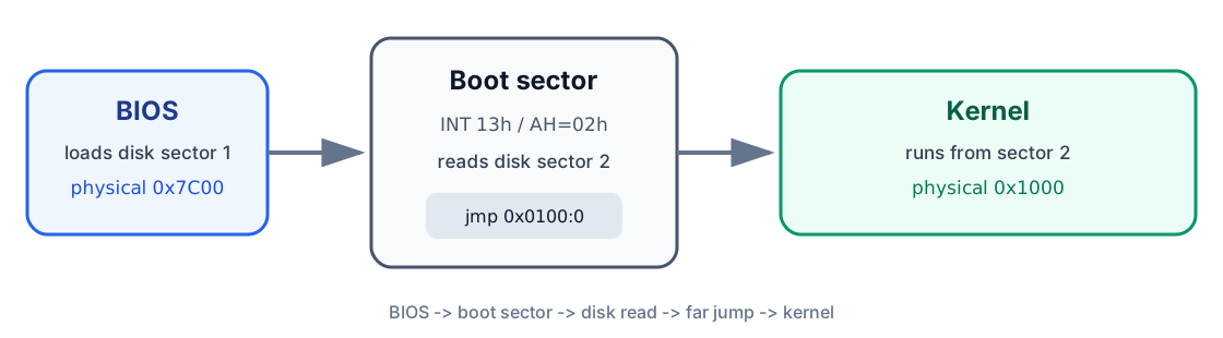
Section titled “What you will build”By the end of the lesson, you will have two 512-byte programs working together instead of one working alone:
| Disk sector | Program | Loaded at | Responsibility |
|---|---|---|---|
| 1 | Boot sector | 0x07C0:0x0000 (physical 0x7C00) |
Ask the BIOS to read the kernel |
| 2 | Kernel | 0x0100:0x0000 (physical 0x1000) |
Print a message to the screen |
This lesson continues Lesson 00 - Writing Your First Boot Sector, which stopped right after printing a message from a boot sector and then halting - a real result, but a dead end. Every boot sector is capped at 512 bytes, and a real operating system needs far more room than that. So here we take the next natural step: use those precious 512 bytes not to do the work, but to go fetch a second program that can.
Lesson 00 introduced the PC’s components, memory addresses, registers, the stack, assembly syntax, and the BIOS boot process that all of this rests on. Keep it nearby if any of those ideas still feel new - this lesson leans on every one of them.
1. Starting point
Section titled “1. Starting point”The previous lesson produced a boot sector that displayed a line of text with
BIOS video service INT 10h, function AH = 0Eh, then stopped forever. It
worked, but it never left its own 512 bytes.
Show the previous lesson's boot-sector program
[BITS 16][ORG 0]
EntryPoint:    cli
    mov ax, 0x07C0    mov ds, ax    mov es, ax
    mov ax, 0x9000    mov ss, ax    mov sp, 0xFFFF
    cld    sti
    mov si, bootMsg    call ShowMsg
.hang:    cli    hlt    jmp .hang
ShowMsg:    push ax    push bx    push si
.loop:    lodsb    test al, al    jz .done
    mov ah, 0x0E    mov bx, 0x0007    int 0x10    jmp .loop
.done:    pop si    pop bx    pop ax    ret
bootMsg db "Peace be upon you!", 13, 10, 0
times 510 - ($ - $$) db 0dw 0xAA55
We will extend that program in two stages:
- Use BIOS disk service
INT 13hto load the kernel. - Write a tiny kernel that prints a second message.
2. How a disk is organized
Section titled “2. How a disk is organized”Inside a floppy’s plastic shell is a flexible disk coated with magnetic material, similar in principle to magnetic tape. The drive encodes stored data as magnetic patterns and decodes those patterns back into binary data when reading - a floppy disk is really just a very small, very slow hard drive wearing a different costume.
The drive itself contains:
- A motor that spins the disk at a fixed speed.
- Two read/write heads, one for each side of the floppy.
- A mechanical arm that moves the heads between the outer edge and the center.
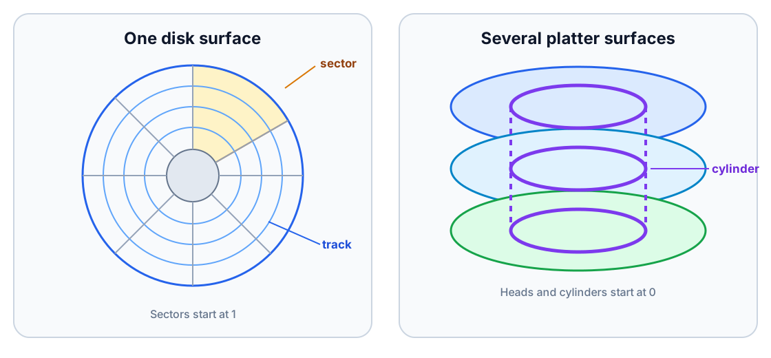
Each disk surface is divided into concentric tracks, the way a vinyl record has grooves circling its surface. Each track is further divided into sectors, and every sector on a standard floppy holds the same amount of data. For this lesson, one sector is 512 bytes - the same size, not coincidentally, as our boot sector.
Hard disks follow the same general idea, but use rigid platters that can spin much faster. A hard disk normally stacks several platter surfaces on top of one another, like a tower of vinyl records sharing a single spindle. Tracks sitting at the same radius on every surface, stacked directly above each other, form a cylinder.
CHS addressing
Section titled “CHS addressing”The BIOS interface used in this lesson identifies a sector with three values:
- Cylinder - the track position from the outer edge toward the center.
- Head - the selected disk surface.
- Sector - the selected sector within that track.
This scheme is called CHS, for cylinder-head-sector - three coordinates that together pin down one exact 512-byte block on the disk, the same way a row, column, and aisle number pin down one shelf in a warehouse.
Data is ordered first by sector, then by head, then by cylinder. On a floppy, the sequence begins with sector 1 on head 0 of cylinder 0. After the last sector on that track, it continues on head 1 of the same cylinder, then moves to cylinder 1.
3. Reading sectors with BIOS INT 13h
Section titled “3. Reading sectors with BIOS INT 13h”In real mode, BIOS interrupt INT 13h provides disk services, the disk
equivalent of the INT 10h video service from Lesson 00. Function AH = 02h
reads one or more sectors using CHS addressing.
Like any BIOS call, it works as a small request form filled out in
registers before you hand it to INT 13h:
Inputs
Section titled “Inputs”| Register | Meaning in this lesson |
|---|---|
ES:BX |
Destination buffer in memory. ES is the segment and BX is the offset. |
AH |
Function number: 02h means “read sectors.” |
AL |
Number of sectors to read. |
CH |
Low eight bits of the cylinder number. We use cylinder 0. |
CL |
Sector number in bits 0-5; the top two cylinder bits are stored in bits 6-7. We use sector 2. |
DH |
Head number. We use head 0. |
DL |
BIOS drive number. Preserve the value supplied by the BIOS instead of assuming drive 0. |
Outputs
Section titled “Outputs”| Carry flag | Result |
|---|---|
CF = 0 |
The read succeeded and the requested data is in memory. |
CF = 1 |
The read failed; AH contains a BIOS status code. |
Unlike the video service, this one can fail - a floppy drive is a mechanical
thing, and mechanical things jam. The carry flag is how the BIOS reports
that back to us, and checking it after every INT 13h call is not optional
caution; it is the only way to notice a bad read before jumping into
whatever garbage happened to land in memory.
At this point the disk layout is simple - two sectors, back to back:
+----------------------+----------------------+| Sector 1 | Sector 2 || boot.bin (512 bytes) | kernel.bin (512 B) |+----------------------+----------------------+The boot sector asks the BIOS to copy sector 2 into ES:BX = 0x0100:0x0000.
| Real-mode address rule | physical address = segment * 16 + offset |
| Kernel destination | 0x0100 * 0x10 + 0x0000 = 0x1000 |
4. Writing the boot sector
Section titled “4. Writing the boot sector”The BIOS places the boot drive number in DL the moment our code starts
running. Save it before performing any disk operation, but only after
initializing DS - the BIOS does not guarantee the initial value of DS,
and a mov [bootdrv], dl executed too early could quietly write to the wrong
place entirely.
The completed boot sector:
; boot.s[BITS 16][ORG 0]
EntryPoint:    ; Establish a known stack and string direction.    cli    mov ax, 0x9000    mov ss, ax    mov sp, 0xFFFF    cld    sti
    ; This source uses offsets relative to segment 0x07C0.    mov ax, 0x07C0    mov ds, ax    mov es, ax
    ; The BIOS tells us which drive booted in DL.    mov [bootdrv], dl
    mov si, bootMsg    call ShowMsg
    ; Reset the boot drive before reading.    mov dl, [bootdrv]    xor ax, ax                    ; AH = 00h: reset disk system    int 0x13    jc readFail
    ; Read cylinder 0, head 0, sector 2 into 0x0100:0x0000.    mov ax, 0x0100    mov es, ax    xor bx, bx    mov ah, 0x02                 ; BIOS read-sector function    mov al, 0x01                 ; read one sector    mov ch, 0x00                 ; cylinder 0    mov cl, 0x02                 ; sector 2    mov dh, 0x00                 ; head 0    mov dl, [bootdrv]    int 0x13    jc readFail
    ; CS:IP becomes 0x0100:0x0000, where the kernel was loaded.    jmp 0x0100:0x0000
readFail:    mov si, readError    call ShowMsg
.hang:    jmp .hang
ShowMsg:    push ax    push bx    push si
.loop:    lodsb    test al, al    jz .done    mov ah, 0x0E                 ; BIOS teletype output    mov bx, 0x0007               ; page 0, light-gray foreground    int 0x10    jmp .loop
.done:    pop si    pop bx    pop ax    ret
bootdrv  db 0bootMsg  db "Peace be upon you!", 13, 10, 0readError db "Error: unable to read the kernel.", 13, 10, 0
times 510 - ($ - $$) db 0dw 0xAA55
The final word 0xAA55 is the boot signature, exactly as in Lesson 00.
Because x86 stores words in little-endian order, it appears on disk as bytes
55 AA at offsets 510 and 511.
What the new code does
Section titled “What the new code does”Everything above mov si, bootMsg should already look familiar from Lesson
00. Here is what got added on top of it:
| Code | Purpose |
|---|---|
mov [bootdrv], dl |
Preserve the drive selected by the BIOS. |
AH = 00h, INT 13h |
Reset the disk service for that drive. |
ES:BX = 0x0100:0 |
Select physical destination 0x1000. |
AH = 02h, AL = 1 |
Read exactly one sector. |
CH = 0, CL = 2, DH = 0 |
Select cylinder 0, sector 2, head 0. |
jc readFail |
Check the carry flag and report a disk error. |
jmp 0x0100:0 |
Perform a 16:16 far jump to the loaded kernel. |
That last jump is the entire point of the lesson in one line: it is the exact moment control leaves the boot sector’s 512 bytes for good and hands the machine to a second, independently loaded program.
5. Writing the kernel
Section titled “5. Writing the kernel”The kernel begins at offset 0 within segment 0x0100, so its source uses
ORG 0. It initializes the data segments and stack exactly the way the boot
sector did, prints a message with the same BIOS video service, and then stops
in an infinite loop - the same shape as Lesson 00’s program, just now living
somewhere else in memory.
; kernel.s[BITS 16][ORG 0]
start:    cli
    ; The boot sector loaded this code at segment 0x0100.    mov ax, 0x0100    mov ds, ax    mov es, ax
    mov ax, 0x9000    mov ss, ax    mov sp, 0xFFFF
    cld    sti
    mov si, kernelMsg    call ShowMsg
.hang:    jmp .hang
ShowMsg:    push ax    push bx    push si
.loop:    lodsb    test al, al    jz .done    mov ah, 0x0E    mov bx, 0x0007    int 0x10    jmp .loop
.done:    pop si    pop bx    pop ax    ret
kernelMsg db "Kernel loaded.", 13, 10, 0
; The boot sector reads one complete 512-byte sector.times 512 - ($ - $$) db 0
Notice that this “kernel” is really just another boot-sector-shaped program - nothing about the format changes. What makes it a kernel in this lesson is only its role: it is the thing the boot sector hands control to, not anything intrinsically different about its bytes. Later lessons will start asking much more of it.
Because both programs use ShowMsg, you can move it to a shared include
file:
%include "showmsg.inc"For a first experiment, keeping the routine in both source files makes each listing self-contained and easier to read start to finish without flipping between files.
6. Assemble the programs
Section titled “6. Assemble the programs”Use NASM’s flat-binary output format:
nasm -f bin boot.s -o boot.binnasm -f bin kernel.s -o kernel.binBoth files should be exactly 512 bytes:
wc -c boot.bin kernel.binExpected result:
512 boot.bin512 kernel.binCreate a two-sector image:
cat boot.bin kernel.bin > aos.imgThe resulting aos.img is 1,024 bytes. It contains the boot sector followed
immediately by the kernel sector and can be attached as a raw floppy image in
an x86 emulator such as Bochs.
Run it in your browser
Section titled “Run it in your browser”The playground uses the same two assembled sectors, padded to a standard
1.44 MiB floppy image. Reaching Kernel loaded. proves that the boot sector
read sector 2 and transferred control to the kernel.
To write the image to floppy drive A on a Unix-like system:
dd if=aos.img of=/dev/fd0 bs=512 conv=fsyncWindows
Section titled “Windows”Create the same two-sector image with:
copy /b boot.bin+kernel.bin aos.imgThey then use ntrawrite to copy the image to a physical floppy:
ntrawrite -f aos.imgWhen prompted for the diskette drive, enter A.
7. Result
Section titled “7. Result”The machine now follows this sequence:
- The BIOS loads and runs the boot sector.
- The boot sector prints
Peace be upon you!. - BIOS disk service
INT 13hcopies sector 2 to physical address0x1000. - A far jump transfers control to
0x0100:0x0000. - The kernel prints
Kernel loaded.and remains in its infinite loop.
The kernel does very little on its own, but the boundary that mattered has already been crossed: code is no longer limited to the 512 bytes the BIOS is willing to load automatically. Anything the boot sector can read from disk, it can now hand control to - a larger kernel, a different program, or, in the next lesson, a completely different CPU mode.
Lesson 02 - Entering 32-bit Protected Mode builds the required descriptor table, changes the processor’s operating mode, and writes directly to VGA text memory from a 32-bit kernel.