Entering 32-bit Protected Mode
What you will build
Section titled “What you will build”Lesson 01 ended with a boot sector that loaded
a second program from disk and jumped straight into it. That was real progress -
but both programs were still living in the CPU’s cozy, BIOS-provided startup
world, asking INT 10h to print every character for us.
This lesson pulls that safety net away. By the end of it, the boot sector will hand the CPU a completely different rulebook for how it sees memory, flip a single bit that changes how every instruction afterward is interpreted, and land in a kernel that talks to the screen hardware directly - no BIOS involved at all.
Concretely, the boot sector will:
- Load a 32-bit kernel from sector 2.
- Describe the memory layout with a Global Descriptor Table, or GDT.
- Enable protected mode in control register
CR0. - Reload the CPU’s code and data segments.
- Transfer control to the kernel at address
0x1000.
The kernel will then clear the display and print:
Protected mode is active.It cannot use the old BIOS printing routine, so it will write characters directly to VGA text memory. That is the payoff moment of this lesson: watching the exact instant a machine stops being “a BIOS with a program attached” and becomes “a program that owns the machine.”
| Item | Location | Purpose |
|---|---|---|
| Boot sector | 0x7C00 |
Load the kernel and change CPU mode |
| Kernel | 0x1000 |
Run 32-bit instructions |
| VGA text buffer | 0xB8000 |
Hold screen characters and colors |
| GDT | Inside the boot sector | Describe the code and data address spaces |
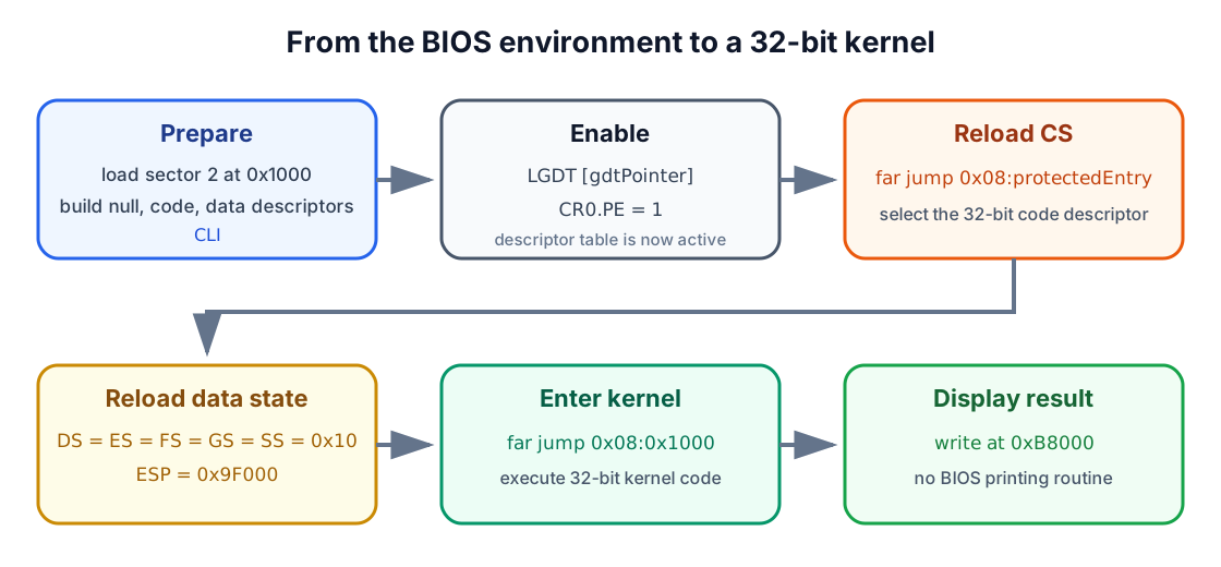
If some of what follows feels dense on a first read, that is completely normal - protected mode touches almost everything about how the CPU thinks about memory. Section 9 retraces the whole transition step by step once every piece is in place, so treat this first pass as building the vocabulary you will use there.
1. How the CPU reaches memory and devices
Section titled “1. How the CPU reaches memory and devices”Lesson 00 introduced the CPU, RAM, storage, and peripherals as separate boxes on a diagram. Before reshaping how the CPU sees memory, it helps to open up what actually happens on the wires between those boxes.
Think of it as a small delivery system. Electronic paths called buses connect the CPU to memory and hardware controllers, and a simplified PC carries four kinds of signal over them:
| Signal group | Job |
|---|---|
| Address | Select a memory location or hardware port |
| Data | Carry the value being read or written |
| Control | Describe the operation, such as read or write |
| Power and timing | Supply energy and coordinate the transfer |
The address bus asks “which mailbox,” the data bus carries “what’s inside,” and the control bus decides whether we are dropping something off or picking something up.
Address width and address space
Section titled “Address width and address space”Every address bus has a fixed number of wires, so it can only spell out so many
distinct addresses. If the CPU has n usable address bits, it can form 2^n
distinct addresses - one for every combination of those wires being high or low,
the same way an n-digit combination lock has 2^n possible combinations.
| Address bits | Number of distinct byte addresses |
|---|---|
| 16 | 2^16 = 65,536 |
| 20 | 2^20 = 1,048,576 (1 MiB) |
| 32 | 2^32 = 4,294,967,296 (4 GiB) |
The original 8086 exposed 20 address lines, covering the first 1 MiB - the entire directory it could ever address. BIOS-compatible startup still preserves that old layout today, quirks and all, including the historical A20 boundary behavior we will deliberately sidestep for now. Later, in the 32-bit flat layout this lesson builds, code can use 32-bit offsets across a full 4 GiB linear address space - 4,096 times larger than anything the 8086 could ever see.
Data width
Section titled “Data width”Address lines pick a location; data lines decide how much you can carry through the door in one trip.
| Width | x86 name |
|---|---|
| 8 bits | Byte |
| 16 bits | Word |
| 32 bits | Doubleword, or dword |
The CPU’s general-purpose registers mirror this split: AX is a 16-bit
register, while EAX is its 32-bit extension - the same register wearing a
bigger handle.
Little-endian byte order
Section titled “Little-endian byte order”Memory is addressed one byte at a time, so when x86 stores something wider than a single byte, it has to decide which piece goes where. Its rule: put the least-significant byte at the lowest address.
For the 16-bit value 0x1234:
| Address | Stored byte |
|---|---|
n |
0x34 |
n + 1 |
0x12 |
This is called little-endian order, and it can trip you up the first time
you inspect raw memory in a debugger and see bytes that look “backwards.” They
are not backwards - the CPU always reads them in this same order, so
reconstructing 0x1234 from 34 12 is automatic once you know the rule.
Three ways to communicate
Section titled “Three ways to communicate”Everything the CPU exchanges with the rest of the machine goes through one of three doors:
- Memory access - the CPU reads and writes addressed bytes in RAM.
- Input/output access - the CPU communicates with a controller through a separate port number or through a memory-mapped region.
- Interrupts - a device or CPU event asks the processor to pause its current sequence and handle an event.
Port numbers live in a completely separate I/O address space; they are not RAM
addresses, even when the numbers look the same. I/O port 0x3D0 and memory
address 0x3D0 are two unrelated things that happen to share some digits.
We will keep interrupts turned off for the entire mode switch in this lesson, because the old BIOS interrupt table stops being valid partway through and we have not built a protected-mode one yet.
2. From startup segmentation to protected mode
Section titled “2. From startup segmentation to protected mode”We deliberately avoided CPU-mode terminology in Lesson 00 so you could focus on the basics first. Now that the boot sector and kernel already cooperate in real mode, it is time to name what “real mode” actually means - and what changes when we leave it.
Real-mode addresses
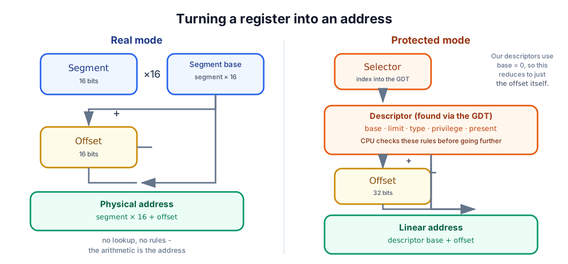
Section titled “Real-mode addresses”The environment the BIOS starts our boot sector in is called real mode - “real” as in close to the original 8086, not as in simple to reason about. An address is formed from a 16-bit segment and a 16-bit offset:
physical address = segment × 16 + offsetBecause the segment gets multiplied by 16 before the offset is added in, many different segment:offset pairs can name the exact same physical byte - similar to how two different room-and-floor combinations can point at the very same door if the numbering overlaps:
0x3415:0x0055 → 0x34150 + 0x0055 → 0x341A50x341A:0x0005 → 0x341A0 + 0x0005 → 0x341A5Our previous lessons leaned on exactly this arrangement:
0x07C0:0x0000 → boot sector at physical 0x7C000x0100:0x0000 → kernel at physical 0x1000This scheme is a direct descendant of the earliest x86 processors, and it is why every address in our lessons so far has had a 16-bit segment:offset spelling. Segment arithmetic can nominally reach slightly beyond 1 MiB on later CPUs; whether those addresses actually wrap around depends on the A20 address line. Everything in this lesson deliberately stays below that boundary, so it will not matter yet.
Protected-mode addresses
Section titled “Protected-mode addresses”Protected mode throws out the “multiply and add” rule entirely, and this is usually the point where the segment:offset mental model stops helping and starts getting in the way. It is fine to let it go here.
In protected mode, a segment register no longer contains a segment base to multiply by 16. It contains a segment selector:
selector : 32-bit offsetThink of the selector less like an address and more like a catalog number: punching it into the CPU does not hand back a memory location directly - it points to a full description of that memory region, kept in a table. That description, the descriptor, is what actually supplies the base address, limit, type, and access rules, and the CPU checks those rules before it lets any access through.
This layer of indirection is exactly what makes features like privilege levels and per-region memory validation possible: the CPU can refuse a selector, or the access that comes with it, before ever touching RAM.
The flat memory model
Section titled “The flat memory model”This lesson creates exactly one code descriptor and one data descriptor - the bare minimum protected mode requires, set up so they get out of the way rather than help. Both have:
- Base address
0. - Limit covering the entire 4 GiB linear address space.
- Privilege level
0, the most privileged level.
Because their base is zero, whatever offset you write is already the corresponding linear address. This is called a flat memory model:
linear address = descriptor base 0 + offsetSegmentation still exists underneath, but from here on it no longer shifts anything - every offset you write in code is the real address.
3. Selectors and the Global Descriptor Table
Section titled “3. Selectors and the Global Descriptor Table”The Global Descriptor Table, or GDT, is where descriptors actually live: an array of 8-byte entries in memory, one entry per segment we want to describe. Ours needs exactly three:
| Index | Selector | Entry |
|---|---|---|
| 0 | 0x00 |
Required null descriptor |
| 1 | 0x08 |
32-bit code segment |
| 2 | 0x10 |
32-bit data and stack segment |
Why does index 1 become selector 0x08 rather than a plain 0x01? Because a
selector is not just a table index - its low three bits are reserved for flags,
and only the remaining bits hold the actual index:
selector = index × 8Therefore:
1 × 8 = 0x08 → code descriptor2 × 8 = 0x10 → data descriptor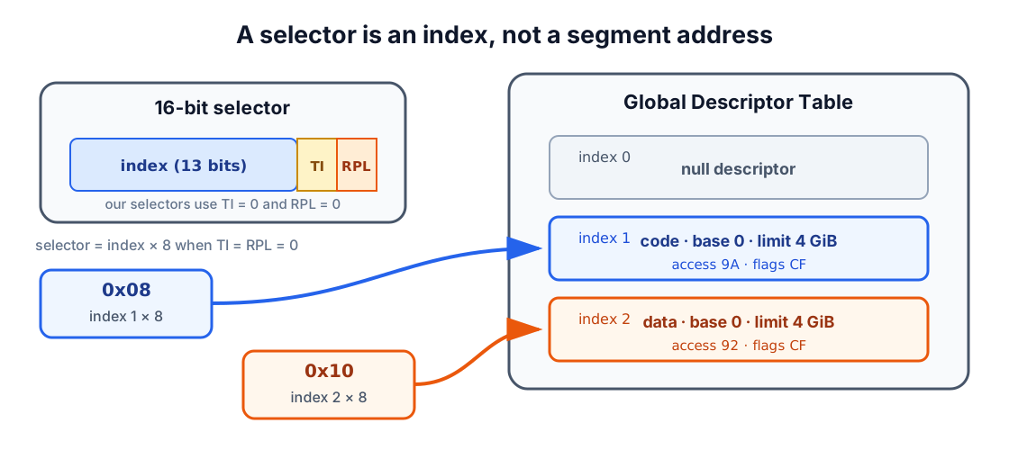
The null descriptor
Section titled “The null descriptor”Index 0 is required to be unusable - not by convention, but by rule. Its job is to make selector zero mean “no segment, deliberately,” instead of accidentally selecting valid memory if a bug ever leaves a segment register at zero.
gdtNull: dq 0DQ defines one 8-byte quantity, so this single line emits eight zero bytes -
the whole entry.
What is inside a descriptor?
Section titled “What is inside a descriptor?”An x86 code or data descriptor packs a surprising amount of information into just 64 bits:
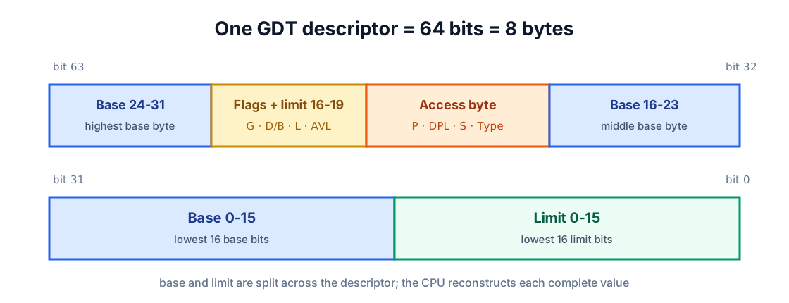
The main fields are:
| Field | Purpose |
|---|---|
| Base | 32-bit starting linear address of the segment |
| Limit | 20-bit maximum offset inside the segment |
| Type | Code/data kind and allowed operations |
S |
1 for a normal code or data descriptor |
DPL |
Privilege level, from 0 to 3 |
P |
Present bit; 1 means the descriptor is usable |
D/B |
1 selects 32-bit code or stack behavior |
G |
Granularity: bytes when 0, 4 KiB units when 1 |
AVL |
Bit available for software use |
The 20-bit limit field can only count up to 0xFFFFF on its own. With G = 1,
though, the CPU reinterprets that count in 4 KiB units instead of bytes,
stretching it to cover every offset through 0xFFFFFFFF - the full 4 GiB range,
out of an 8-byte structure designed long before flat addressing existed.
Our code descriptor
Section titled “Our code descriptor”gdtCode: dw 0xFFFF dw 0x0000 db 0x00 db 10011010b db 11001111b db 0x00Laid out as raw bytes, our fields become:
FF FF 00 00 00 9A CF 00Read left to right, the access byte 0x9A says present, ring 0, a normal
code/data-style descriptor, executable, and readable. The flags/limit byte
0xCF is doing two jobs at once: its top nibble turns on 4 KiB granularity and
32-bit behavior, and its bottom nibble supplies the high four bits of the limit.
Our data descriptor
Section titled “Our data descriptor”gdtData: dw 0xFFFF dw 0x0000 db 0x00 db 10010010b db 11001111b db 0x00Its access byte 0x92 swaps “executable” for “writable” - present, ring 0,
writable data - while the base, limit, and 32-bit/granularity flags stay
identical to the code descriptor. Same shape, different job.
Telling the CPU where the GDT lives
Section titled “Telling the CPU where the GDT lives”Building the table is only half the job - the CPU also needs to be told where to find it. That is what the GDTR register is for. It holds:
- A 16-bit table limit, stored as table size minus one.
- A 32-bit linear base address.
Our pointer is:
gdtPointer: dw gdtEnd - gdtStart - 1 dd BOOT_ADDRESS + gdtStartgdtStart is an offset, not an address, because the boot source uses [ORG 0].
Adding the physical boot address 0x7C00 turns that offset into the linear
address LGDT actually needs.
4. The mode-switch sequence
Section titled “4. The mode-switch sequence”Here is the part that makes people nervous the first time, and honestly deserves a little reverence: the actual mode switch. It is short - seven steps - but the order genuinely matters. Skip one, or run them out of sequence, and the CPU is happy to reset itself before you ever find out why.
Step 1: disable interrupts
Section titled “Step 1: disable interrupts”cliThe old BIOS interrupt table stops being trustworthy the moment we change modes
- it was built for real mode, and a hardware interrupt landing mid-transition would send the CPU to a handler meant for an environment we are actively leaving. We hold interrupts off until a later lesson builds the protected-mode structures and handlers this requires.
Step 2: load the GDT register
Section titled “Step 2: load the GDT register”lgdt [gdtPointer]LGDT copies the limit and base out of gdtPointer and into the CPU’s GDTR
register. Nothing moves in memory - the descriptors stay exactly where we wrote
them; the CPU now simply knows where to look them up.
Step 3: set the protected-enable bit
Section titled “Step 3: set the protected-enable bit”Control register CR0 holds system-wide CPU settings, and its least-significant
bit - PE, the protected-enable bit - is the one that matters here. Flipping it
is the single moment the CPU’s behavior actually changes:
mov eax, cr0or eax, 0x00000001mov cr0, eaxWe read the existing value, OR in just the bit we care about, and write it
back - preserving every other control bit CR0 happens to hold, rather than
guessing what a “clean” value would look like.
Step 4: reload the code segment
Section titled “Step 4: reload the code segment”Setting CR0.PE does not retroactively fix CS - the CPU keeps using its
cached, real-mode idea of the current code segment until something explicitly
reloads it. A far jump is that something: it loads CS with selector 0x08
and, in the same instruction, starts fetching through our new 32-bit code
descriptor:
jmp dword CODE_SELECTOR:(BOOT_ADDRESS + protectedEntry)Because the code descriptor’s base is zero, the jump’s target must already be a
linear address. protectedEntry is only an offset inside a sector loaded at
0x7C00, which is exactly why the expression adds BOOT_ADDRESS back in -
otherwise we would land in the wrong place by exactly 0x7C00 bytes.
Step 5: assemble the new instructions as 32-bit code
Section titled “Step 5: assemble the new instructions as 32-bit code”[BITS 32]protectedEntry:BITS 32 is purely a message to NASM, not to the CPU. It tells the assembler to
encode everything below this line as 32-bit instructions. It does not switch
the CPU by itself - by the time execution reaches here, the GDT, CR0.PE, and
the far jump have already done that job. BITS 32 just makes sure the bytes
NASM emits actually match what the CPU is now expecting to decode.
Step 6: reload data segments and the stack
Section titled “Step 6: reload data segments and the stack”mov ax, DATA_SELECTORmov ds, axmov es, axmov fs, axmov gs, axmov ss, axmov esp, 0x0009F000Loading selector 0x10 into each data-related register makes the CPU cache our
flat data descriptor for each of them. ESP takes over as the stack pointer in
place of the old 16-bit SP, pointed at a comfortably empty region below
0xA0000.
Step 7: jump to the loaded kernel
Section titled “Step 7: jump to the loaded kernel”jmp dword CODE_SELECTOR:KERNEL_ADDRESSThe code descriptor’s base is zero and the kernel sits at linear address
0x1000, so the new CS:EIP becomes 0x08:0x00001000 - the first instruction
of the kernel we loaded, back before any of this mode-switching began.
5. Complete boot-sector source
Section titled “5. Complete boot-sector source”Here is everything from the previous sections assembled into one file: the corrected Lesson 01 disk loader, the GDT, the transition code, and the BIOS error message, laid out in the order the CPU actually runs through them.
Show lesson 02/src/boot.asm
; AOS Lesson 02 - Entering 32-bit protected mode
[BITS 16][ORG 0]
%define BOOT_SEGMENT    0x07C0%define BOOT_ADDRESS    0x7C00%define KERNEL_SEGMENT  0x0100%define KERNEL_ADDRESS  0x1000
%define CODE_SELECTOR   0x08%define DATA_SELECTOR   0x10
start:    ; Establish known data segments and a safe stack.    cli
    mov ax, BOOT_SEGMENT    mov ds, ax    mov es, ax
    mov ax, 0x9000    mov ss, ax    mov sp, 0xFFFF
    cld    sti
    ; Preserve the drive selected by the BIOS.    mov [bootDrive], dl
    mov si, loadingMessage    call printString
    ; Reset the boot drive.    mov dl, [bootDrive]    xor ax, ax    int 0x13    jc diskError
    ; Read sector 2 into physical address 0x1000.    mov ax, KERNEL_SEGMENT    mov es, ax    xor bx, bx    mov ah, 0x02    mov al, 0x01    mov ch, 0x00    mov cl, 0x02    mov dh, 0x00    mov dl, [bootDrive]    int 0x13    jc diskError
    ; Install the descriptor table and enable protected mode.    cli    lgdt [gdtPointer]
    mov eax, cr0    or eax, 0x00000001    mov cr0, eax
    ; Reload CS through the 32-bit code descriptor.    jmp dword CODE_SELECTOR:(BOOT_ADDRESS + protectedEntry)
diskError:    mov si, diskErrorMessage    call printString
.hang:    cli    hlt    jmp .hang
printString:    push ax    push bx    push si
.loop:    lodsb    test al, al    jz .done
    mov ah, 0x0E    mov bx, 0x0007    int 0x10    jmp .loop
.done:    pop si    pop bx    pop ax    ret
; ---------------------------------------------------------------------------; Global Descriptor Table; ---------------------------------------------------------------------------
gdtStart:gdtNull:    dq 0
gdtCode:    dw 0xFFFF               ; limit bits 0-15    dw 0x0000               ; base bits 0-15    db 0x00                 ; base bits 16-23    db 10011010b            ; present, ring 0, code, readable    db 11001111b            ; 4 KiB granularity, 32-bit, limit bits 16-19    db 0x00                 ; base bits 24-31
gdtData:    dw 0xFFFF               ; limit bits 0-15    dw 0x0000               ; base bits 0-15    db 0x00                 ; base bits 16-23    db 10010010b            ; present, ring 0, data, writable    db 11001111b            ; 4 KiB granularity, 32-bit, limit bits 16-19    db 0x00                 ; base bits 24-31gdtEnd:
gdtPointer:    dw gdtEnd - gdtStart - 1    dd BOOT_ADDRESS + gdtStart
loadingMessage   db "Loading the 32-bit kernel...", 13, 10, 0diskErrorMessage db "Error: unable to read the kernel.", 13, 10, 0bootDrive        db 0
; ---------------------------------------------------------------------------; First instructions after CR0.PE becomes 1; ---------------------------------------------------------------------------
[BITS 32]protectedEntry:    mov ax, DATA_SELECTOR    mov ds, ax    mov es, ax    mov fs, ax    mov gs, ax    mov ss, ax    mov esp, 0x0009F000
    ; The kernel was loaded at linear address 0x1000.    jmp dword CODE_SELECTOR:KERNEL_ADDRESS
times 510 - ($ - $$) db 0dw 0xAA55
6. Display output without the BIOS
Section titled “6. Display output without the BIOS”Once CS points at our own descriptor and EIP is inside the kernel, INT 10h
is gone - not disabled, just meaningless, since the BIOS’s real-mode interrupt
vectors were never valid for the CPU state we are in now. If we want a single
character to appear on screen, we have to talk to the video hardware ourselves.
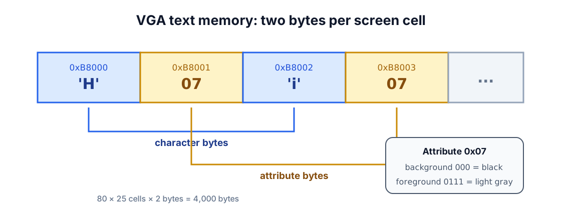
In the standard color text layout, the graphics card exposes the screen as a
block of memory starting at 0xB8000: write a character there, and it appears,
no interrupt required. An 80-column by 25-row display has:
80 × 25 = 2,000 character cellsEach cell occupies two bytes:
- The character’s text code.
- Its color attribute.
The complete screen therefore occupies 2,000 × 2 = 4,000 bytes - small enough
to clear or repaint in a tight loop, with no help from the BIOS.
The attribute byte
Section titled “The attribute byte”The attribute byte works like a compact color code. The low four bits select the foreground color, bits 4-6 select the background color, and bit 7 traditionally controls blinking when that feature is enabled.
0x07 means:
background = 000 (black)foreground = 0111 (light gray)Clearing the screen
Section titled “Clearing the screen”The kernel writes a space and attribute 0x07 to every cell:
mov ebx, VIDEO_MEMORYmov ecx, SCREEN_CELLS
.clearScreen:    mov byte [ebx], ' '    mov byte [ebx + 1], TEXT_ATTRIBUTE    add ebx, 2    loop .clearScreen
ECX begins at 2,000, one decrement per cell. LOOP handles both the
decrement and the “repeat while nonzero” check in a single instruction, while
EBX advances two bytes at a time to keep pace with each character/attribute
pair.
Printing the message
Section titled “Printing the message”The message is still nothing more exotic than a null-terminated string, just like the ones printed through the BIOS in earlier lessons:
message db "Protected mode is active.", 0ESI points to the next message byte and EBX points to the next display
cell - the same “read a byte, stop at the null” pattern from Lesson 00 and
Lesson 01, just aimed at video memory instead of INT 10h this time:
mov esi, messagemov ebx, VIDEO_MEMORY
.printCharacter:    lodsb    test al, al    jz .hang
    mov byte [ebx], al    mov byte [ebx + 1], TEXT_ATTRIBUTE    add ebx, 2    jmp .printCharacter
Because the data descriptor has base zero and the kernel uses [ORG 0x1000],
NASM already encodes message as its correct linear address in the loaded
kernel - no extra arithmetic needed here, unlike the boot sector’s
protectedEntry jump.
7. Complete 32-bit kernel
Section titled “7. Complete 32-bit kernel”; AOS Lesson 02 - 32-bit kernel
[BITS 32][ORG 0x1000]
%define VIDEO_MEMORY 0x000B8000%define SCREEN_CELLS (80 * 25)%define TEXT_ATTRIBUTE 0x07
start: cld
; Clear the 80 x 25 text screen. mov ebx, VIDEO_MEMORY mov ecx, SCREEN_CELLS
.clearScreen: mov byte [ebx], ' ' mov byte [ebx + 1], TEXT_ATTRIBUTE add ebx, 2 loop .clearScreen
; Print the null-terminated message. mov esi, message mov ebx, VIDEO_MEMORY
.printCharacter: lodsb test al, al jz .hang
mov byte [ebx], al mov byte [ebx + 1], TEXT_ATTRIBUTE add ebx, 2 jmp .printCharacter
.hang: cli hlt jmp .hang
message db "Protected mode is active.", 0CLI and HLT bring it to a quiet, permanent stop, because there is no
operating system yet to return control to, and no protected-mode interrupt
table to safely catch a stray interrupt.
8. Build the disk image
Section titled “8. Build the disk image”With both source files ready, the repository’s Makefile does the mechanical work: assembling both programs, checking their sizes, and writing them to the correct disk sectors.
make -C "lesson 02"make -C "lesson 02" inspectExpected output:
boot sector: 512 bytessignature: 55 aakernel: 79 bytesCreate the floppy image:
make -C "lesson 02" imageIts first two sectors are:
| Disk location | Contents |
|---|---|
Sector 1, bytes 0-511 |
boot.bin |
Sector 2, starting at byte 512 |
kernel.bin, followed by zeroes |
Run it in your browser
Section titled “Run it in your browser”This playground boots the same floppy image in v86. Reaching Protected mode is active. proves that the loader read the kernel, installed the GDT, enabled
protected mode, entered 32-bit code, and wrote directly to VGA memory.
If qemu-system-i386 is installed, this is the moment to actually see it
happen:
make -C "lesson 02" runThe virtual machine first flashes the familiar BIOS-assisted loading message -
proof the boot sector still works the old way for that one line - and then, the
instant protected mode takes over, the screen clears and Protected mode is active. appears, written by the kernel with its own hands.
9. Trace the complete transition
Section titled “9. Trace the complete transition”Now that every piece exists, it is worth walking the whole sequence once more end to end - the “big picture” version of everything Section 4 covered one step at a time.
| Step | CPU state |
|---|---|
| 1 | BIOS loads sector 1 at 0x7C00 |
| 2 | Boot sector reads sector 2 into 0x1000 |
| 3 | LGDT loads the GDT base and limit |
| 4 | CR0.PE becomes 1 |
| 5 | Far jump loads CS = 0x08 and enters 32-bit code |
| 6 | DS, ES, FS, GS, and SS receive selector 0x10 |
| 7 | ESP receives the new 32-bit stack address |
| 8 | Far jump transfers control to 0x08:0x1000 |
| 9 | Kernel clears and writes the VGA text buffer |
| 10 | Kernel halts |
There is no single “switch to 32-bit” instruction anywhere in x86, and that
trips people up constantly when they go looking for one. What actually happens
is the combination you just traced: a valid GDT, CR0.PE, the far jump that
reloads CS, and the 32-bit descriptor selected by that jump. Miss any one
piece, and the CPU is happy to run into undefined behavior instead of politely
refusing.
10. Troubleshooting
Section titled “10. Troubleshooting”Bare-metal debugging has no stack trace and no error message - usually just a silent reset or a blank screen. That is disorienting the first few times, so here is a map from symptom back to the step that is probably still wrong.
| Symptom | Likely cause |
|---|---|
| The machine immediately resets. | A bad GDT, selector, or transition address may have caused an exception before an IDT existed. |
| Only the loading message appears. | Check the GDT pointer, CR0.PE, far jump, and kernel sector placement. |
| The screen clears but shows no message. | Check the kernel’s [ORG 0x1000], ESI, null terminator, and DS = 0x10. |
| The display contains odd colors or characters. | Check the character/attribute byte order and the 0xB8000 base. |
| BIOS printing stops working after the transition. | Expected: the protected-mode kernel writes directly to VGA memory instead. |
| NASM reports that the boot sector is too large. | Code and data have exceeded the 510 bytes available before the signature. |
11. What you have learned
Section titled “11. What you have learned”You crossed a real boundary in this lesson, not just an incremental one: everything before ran inside safety rails the BIOS built for you, and everything from here on runs inside rails the kernel builds for itself. Along the way, you now have a loader that:
- Understands both the startup segment:offset calculation and protected-mode selectors.
- Defines a null, code, and data descriptor.
- Loads the GDT with
LGDT. - Enables protected mode through
CR0.PE. - Uses far jumps to reload
CSand enter the kernel. - Establishes flat 32-bit code, data, and stack segments.
- Writes characters directly to VGA text memory without BIOS services.
Lesson 03 - Starting a C++ Kernel swaps this hand-written kernel for a higher-level C++ one loaded by GRUB through the Multiboot specification - the assembly you just wrote will not go to waste, though. It is exactly the ground truth that higher-level bootloader is built on top of.