Managing Interrupts and Exceptions
What you will build
Section titled “What you will build”Lesson 03 ended the moment it had said
everything it had to say: kmain printed a greeting and the machine’s memory
information, then sat in cli; hlt forever. That is not a kernel - it is a
program that runs once. A real kernel spends almost all of its life waiting
for something to happen and reacting when it does: a key goes down, a timer
tick arrives, a division by zero goes wrong somewhere in a driver you have
not written yet. All three are interrupts, and this lesson is about
building the machinery that catches them.
By the end, kmain will still print the same boot banner - but it will no
longer stop there. It will:
- Build an Interrupt Descriptor Table (IDT), protected mode’s version of the address book the CPU consults on every interrupt.
- Reprogram the 8259 Programmable Interrupt Controller (PIC), the chip that turns keyboard presses and timer ticks into something the CPU can see - because left at its factory settings, it hands out the exact same numbers the CPU already reserves for its own exceptions.
- Route every one of those 48 numbered events through a single, shared piece
of assembly into ordinary C++ objects -
Exceptionfor CPU faults,Timerfor a real, ticking piece of hardware.
Concretely, four new source files join the ones Lesson 03 already built:
| File | Responsibility |
|---|---|
interrupt.h |
One abstract Interrupt class every handler implements |
isr.h / isr.cpp |
Builds the IDT and dispatches each vector to a registered handler |
asm.inc / isrs.s |
48 tiny assembly stubs plus the shared save/restore/dispatch code |
pic.h / pic.cpp |
Initializes and talks to the 8259 PIC |
exception.h / exception.cpp |
A handler that reports CPU faults instead of silently hanging |
timer.h / timer.cpp |
A handler driven by the Programmable Interval Timer, ticking once a second |
![A hardware event or CPU exception makes the CPU consult idt[vector] and jump into isrN in isrs.s, which pushes an error code and vector number before falling into the shared isrCommon. isrCommon saves every register, calls isrDispatch in isr.cpp, which looks up handlers[vector] and calls its handle method, then control returns through isrCommon, which restores registers and executes iret. Below, the stack at the moment isrDispatch runs holds eflags, cs, and eip pushed by the CPU, the error code and vector pushed by the stub, and the saved registers that make up the regs structure.](/aos/_astro/isr-dispatch-flow.DNEEYFBQ_G0Fm6.svg)
1. Three kinds of interrupt, and why the CPU treats them differently
Section titled “1. Three kinds of interrupt, and why the CPU treats them differently”“Interrupt” is a convenient umbrella word, but x86 actually distinguishes three sources, and the difference matters for how you handle each one:
| Kind | Triggered by | Timing | Example |
|---|---|---|---|
| Exception | The CPU itself, mid-instruction | Synchronous - always tied to the instruction that caused it | Division by zero, page fault |
| IRQ | External hardware, through the PIC | Asynchronous - can arrive between any two instructions | Keyboard key, timer tick |
| Software interrupt | An explicit int, int3, into, or bound instruction |
Synchronous, but deliberate | Real-mode BIOS calls (not used here - we are in protected mode) |
Exceptions further split into three flavors, depending on exactly when they are reported relative to the instruction that caused them:
- Faults - reported before the instruction completes;
eipis saved pointing at the faulting instruction, so a fault handler that fixes the problem and returns will retry it from scratch. - Traps - reported after the instruction completes; the saved
eipalready points at the next instruction. - Aborts - reserved for damage severe enough that resuming the interrupted program is not considered safe.
The x86 architecture reserves the first 32 interrupt vectors - 0 through 31 -
for these CPU-defined exceptions. Vectors 32 through 255 are free for anyone
else to use, which is exactly what a PIC-driven IRQ or a software int does.
Of the 32 reserved vectors, a handful push an extra 32-bit error code onto the stack right before jumping to the handler - Double Fault, Invalid TSS, Segment Not Present, Stack Fault, General Protection Fault, and Page Fault all do. The rest push nothing at all. Section 4’s assembly stubs exist almost entirely to paper over that one inconsistency.
2. Why the 8259 PIC has to be reprogrammed before it is safe to use
Section titled “2. Why the 8259 PIC has to be reprogrammed before it is safe to use”Keyboard presses and timer ticks do not interrupt the CPU directly - they go through the 8259 Programmable Interrupt Controller (PIC), a pair of chips (a master and a slave, cascaded together) that turn up to 16 wired IRQ lines into a single interrupt request the CPU actually sees.
Left at its power-on defaults, the master PIC delivers IRQ0-IRQ7 as
interrupt vectors 8 through 15 - and the slave, on many BIOSes, delivers
IRQ8-IRQ15 starting somewhere else entirely. Either way, those numbers
collide head-on with the CPU’s own reserved exception vectors from Section 1:
vector 8 is both “the timer just ticked” and “Double Fault just happened,”
depending entirely on who you ask.
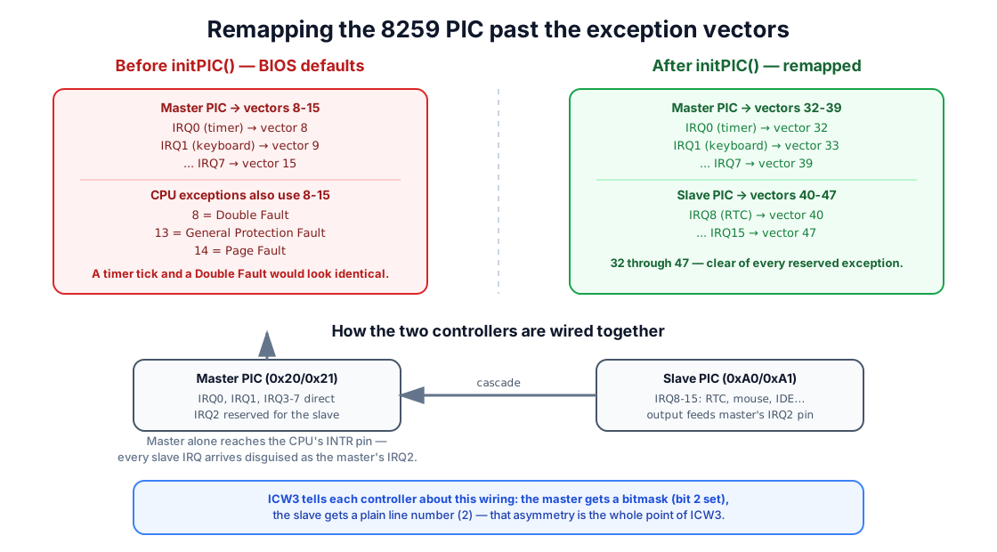
initPIC() fixes this by walking both controllers through their
Initialization Command Words (ICW1-ICW4), a four-byte handshake each PIC
expects in strict order:
const int pic1= 0x20;const int pic2= 0xA0;
void initPIC() {
  //ICW1: need ICW4, pic2 present, edge detetction  outb(pic1, 0x11);  outb(pic2, 0x11);
  /*ICW2: remap pic1 to use vectors from 0x20 (32)  ***    remap pic2 to use vectors from 0x28 (40)  * */  outb(pic1+1, 0x20);  outb(pic2+1, 0x28);
  //ICW3: pic2 uses IRQ2  outb(pic1+1, 4);  outb(pic2+1, 2);
  //ICW4  outb(pic1+1, 1);  outb(pic2+1, 1);
  //mask all irqs initially  setPIC1Mask(0xFF);  setPIC2Mask(0xFF);}
Reading the four words in order:
- ICW1 (
0x11, written to each controller’s command port) announces that ICW4 is coming, that the two controllers are cascaded, and asks for edge-triggered detection - the conventional choice for PC-style IRQ lines. - ICW2 is the one that actually matters here: it tells each controller
which vector its first IRQ line should map to.
0x20is decimal 32, so the master now answersIRQ0with vector 32 instead of 8;0x28is 40, so the slave’sIRQ8becomes vector 40. Both ranges land safely past vector 31. - ICW3 describes the cascade wiring itself, and - unusually - means
something different on each side: the master gets a bitmask (
4= bit 2 set) naming which of its own eight lines the slave is plugged into, while the slave gets a plain line number (2) identifying that same connection from its own side. - ICW4 is a fixed
1on both controllers for a plain x86 setup like this one.
Once initialized, every IRQ line is immediately masked - setPIC1Mask(0xFF)
and setPIC2Mask(0xFF) disable all sixteen lines. That is deliberate: an
interrupt controller that is ready but has nothing registered to catch its
interrupts is far more dangerous than one that is simply quiet. Section 7
unmasks exactly one line, once a handler actually exists for it.
The remaining PIC functions are short, deliberate wrappers around single I/O writes:
// disable irqs specified in maskvoid setPIC1Mask(BYTE mask) {  /* to set the int mask, we use the OCW1   * we write it to 0x21 port, each bit   * correspond to an irq line */  outb(pic1+1, mask);}
//same as bove, but for the salve PICvoid setPIC2Mask(BYTE mask) {  outb(pic2+1, mask);}
/* we must send an EOI to PIC, to reenable * the interrupted irq line */void acknowledgePIC1() {  /* EOI is sent by writing the OCW2 (=0x20   * non specific EOI in our case)to 0x20 port*/  outb(pic1, 0x20);}
void acknowledgePIC2() { // we must send EOI ti both controllers outb(pic1, 0x20); outb(pic2, 0x20);}setPIC1Mask/setPIC2Mask write an Operation Command Word (OCW1): a
plain bitmask where a 1 bit disables that line and a 0 bit enables it -
unlike the ICWs, these can be sent again at any time, not just during setup.
acknowledgePIC1/acknowledgePIC2 send an End Of Interrupt (EOI), and
Section 6’s Timer depends on it completely:
3. The Interrupt Descriptor Table: one entry per vector
Section titled “3. The Interrupt Descriptor Table: one entry per vector”Just as protected mode replaced real mode’s segment-based addressing with a
table of descriptors (the GDT, back in Lesson 03),
it replaces real mode’s simple Interrupt Vector Table with a richer
Interrupt Descriptor Table (IDT) - one 8-byte gate descriptor per vector,
0 through 255, loaded into the CPU with the same kind of pointer-and-limit
structure LGDT uses, this time via LIDT.
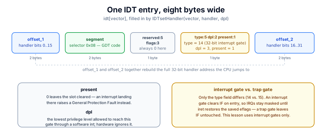
struct IDTEntry {  WORD offset_1;     // offset 0..15  WORD segment;       // segment selector  BYTE reserved:5;  BYTE flags:3;       // 0 for interrupt/trap gates  BYTE type:5;         // type of gate  BYTE dpl:2;  BYTE present:1;  WORD offset_2;} __attribute__((packed));
// Structure to be loaded into the IDTRstruct IDTR {    WORD limit;    DWORD base;} __attribute__((packed));
#define MAX_ENTRIES 256IDTEntry idt[MAX_ENTRIES];static Interrupt* handlers[MAX_ENTRIES];IDTR idtr;
handlers[] sits right next to the IDT itself: the table tells the CPU
where to jump, and handlers[] tells our own dispatcher which C++ object
should actually answer. Building the table is a two-step affair, matching
the GDT’s GDTSetup()/setGDTEntry() split almost exactly:
void IDTSetup() {  //clear all enries for the moment  memset((BYTE*)&idt, 0, sizeof(IDTEntry)*MAX_ENTRIES);
  //initialzes and load the idtr register  idtr.base = (DWORD)&idt;  idtr.limit = sizeof(IDTEntry)*MAX_ENTRIES-1;  asm volatile ("lidt %0"  :: "m"(idtr));}
// this function set a handler for that vectorextern "C" void IDTsetHandler(int vector, DWORD handler, int dpl) {  if(vector < 0 || vector >= MAX_ENTRIES) {    return;  } else if(!handler) {    memset((BYTE*)&(idt[vector]), 0, sizeof(IDTEntry));  } else {    idt[vector].segment = 8;    idt[vector].offset_1 = handler & 0xFFFF;    idt[vector].offset_2 = (handler>>16) & 0xFFFF;    idt[vector].type = 14; //gate's type = interrupt gate    idt[vector].dpl = dpl & 3;    idt[vector].present = 1;  }}
IDTSetup() zeroes all 256 entries - an entry with present = 0 makes any
interrupt landing there raise a General Protection Fault instead of jumping
into garbage - then points IDTR at the table exactly the way GDTR points
at the GDT. IDTsetHandler fills in one entry at a time: segment = 8
names the flat code descriptor GDTSetup() built in Lesson 03, offset_1
and offset_2 split the 32-bit handler address across the descriptor’s two
halves, and type = 14 marks this as a 32-bit interrupt gate - as
opposed to a trap gate (type = 15), whose only real difference is that an
interrupt gate clears the CPU’s interrupt flag on entry, holding off further
IRQs until iret restores the saved flags. Every handler in this lesson
uses an interrupt gate.
4. From a raw CPU event to a C++ call: the assembly stubs
Section titled “4. From a raw CPU event to a C++ call: the assembly stubs”The CPU does not know how to call a C++ function with a vector and an
errorCode argument - it only knows how to push a fixed frame and jump to
whatever address the matching IDT entry names. Bridging that gap is
isrs.s’s entire job, and it starts with a small set of NASM macros in
asm.inc:
;; this macro pushs all the args;; example: PUSHS eax, ebx, ecx...%macro PUSHS 1-*  %rep %0    push %1    %rotate 1  %endrep%endmacro
;; this is the pop equivalent of the above macro;; attention!! args must be provided in the same;; order in PUSHS%macro POPS 1-*  %rep %0    %rotate -1    pop %1  %endrep%endmacro
PUSHS eax, ebx, ecx simply expands to three push instructions in order;
POPS eax, ebx, ecx expands to three pop instructions in the reverse
order, so the same argument list restores exactly what was saved. Two more
macros, c_call and c_extern, exist purely to paper over one build-time
detail: some toolchains prefix every C symbol with an underscore, and the
LEADING_USCORE define (set from the Makefile, Lesson 03’s
own %ifdef trick) decides once, in one place, whether call kmain or
call _kmain is the correct instruction to emit.
With those in hand, isrs.s writes one tiny stub per vector:
;; some macros will facilitate out coding;; INTR generates the code for interruptions;; that dont push an error code%macro INTR 1isr%1:  push dword 0    ; pushes dummy error code  push dword %1    ; push the vector  jmp isrCommon%endmacro
;; interrupts that push error code%macro INTR_EC 1isr%1:  push dword %1    ; push the vector  jmp isrCommon%endmacro
;; generates code in cascade for multiples;; isrs using the above INTR macro%macro MAKE_INTR 2%assign i %1%rep (%2-%1+1)  INTR i  %assign i i+1%endrep%endmacro
Writing isr0, isr1, … isr47 out by hand would mean the same three
lines repeated 48 times, differing only in one number - exactly the kind of
repetition a macro exists to remove. INTR handles the ordinary case: push
a dummy 0 so every stub leaves an error code on the stack whether the CPU
supplied a real one or not, then push the vector number itself, then fall
into the code every stub shares. INTR_EC is the same idea for the six
vectors that already pushed a real error code - no dummy needed, just the
vector. MAKE_INTR generates a whole contiguous run of INTR stubs at
once, so the full set collapses to three lines:
MAKE_INTR 0,7
INTR_EC 8INTR 9INTR_EC 10INTR_EC 11INTR_EC 12INTR_EC 13INTR_EC 14
MAKE_INTR 15, 47
Vectors 8, 10, 11, 12, 13, and 14 - Double Fault, Invalid TSS, Segment Not
Present, Stack Fault, General Protection Fault, and Page Fault - are exactly
the six exceptions Section 1 named as pushing their own error code; every
other vector from 0 to 47 gets the dummy-0 treatment instead.
Every one of those 48 stubs ends the same way, in isrCommon:
isrCommon:  ; save registers on the stack  PUSHS eax,ebx,ecx,edx,edi,esi,ebp,ds,es,fs,gs,ss
  ; ensures segment registers loaded with  ; correct values    mov ax, 0x10    mov ds, ax    mov es, ax    mov fs, ax    mov gs, ax
    c_call isrDispatch
  POPS  eax,ebx,ecx,edx,edi,esi,ebp,ds,es,fs,gs,ss  add esp, 8  ; discard [dummy] error code & vector number  iret
PUSHS saves every general-purpose and segment register the interrupted
code was using, in one fixed order; those twelve values, plus the error
code, vector, and the eflags/cs/eip the CPU itself already pushed,
together form the stack layout the diagram above shows. mov ax, 0x10
reloads the segment registers with the flat data selector - the interrupted
code might have been running with different values, and the handler needs
known-good ones. c_call isrDispatch hands control to C++; when it returns,
POPS restores every register to its saved value, add esp, 8 discards the
error code and vector the stub itself pushed (the CPU does not expect those
back), and iret - not a plain ret - pops eip, cs, and eflags in one
instruction, resuming the interrupted code exactly where it left off.
One piece of assembly remains: getting all 48 stub addresses into the IDT.
A small macro builds one setHandler call per vector, and initISRS runs
all 48 of them:
%macro setHandler 1  push dword 0    ;; kernel-only interrupt gate  push dword isr%1  ;; handler = isr%1 {isr0, isr1...}  push dword %1    ;; interrupt vector  c_call IDTsetHandler  add esp, 12%endmacro
proc  initISRS  push ebp  mov ebp, esp
  %assign i 0  %rep 48    setHandler i    %assign i i+1  %endrep
leave retendprocproc/endproc (from asm.inc) is one more small macro: it declares a
symbol both with and without a leading underscore, so initISRS is callable
from C++ regardless of which naming convention this build’s toolchain
expects - the same problem c_call solves, solved once for definitions
instead of calls.
The first argument passed to IDTsetHandler is the vector and the last is
the gate’s Descriptor Privilege Level. These gates use DPL 0 because they are
kernel entry points, not a public software-interrupt API. Hardware can still
deliver an IRQ through a DPL 0 gate; DPL only restricts explicit int
instructions issued by less-privileged code.
With the assembly side in place, isr.cpp is what actually looks the
vector up and calls into an object:
//this is the default handler, it will call// the handler registered with this vectorextern "C" void isrDispatch(regs r, int vector, int errorCode) {  if(vector < 0 || vector >= MAX_ENTRIES)    return;  if(handlers[vector])    handlers[vector]->handle(&r, vector, errorCode);}
void registerHandler(BYTE vector, Interrupt *interrupt) {  handlers[vector] = interrupt;}
void unregisterHandler(BYTE vector) {  handlers[vector] = (Interrupt*)null;}
isrDispatch receives the saved register block by value - the compiler
copies it once from the stack isrCommon built - then passes its address
to whichever handler is registered, or does nothing at all if the slot is
empty. registerHandler and unregisterHandler are the only two functions
anything outside isr.cpp ever needs to call.
5. One interface, two kinds of handler: Interrupt
Section titled “5. One interface, two kinds of handler: Interrupt”Every handler - a CPU exception, a timer tick, eventually a keyboard key -
needs to answer the same question: given a vector and an optional error
code, what do you do? interrupt.h names that contract as a single pure
virtual method:
class Interrupt { public: virtual void handle(regs *r, int vector, int errorCode)=0;};The =0 makes Interrupt an abstract class - nothing can construct one
directly, only a class that actually implements handle(). That is
precisely the design Lesson 03 flagged as
safe without a heap or global constructors: Exception and Timer below
are both local, stack-allocated objects with virtual functions, and nothing
more exotic than that.
6. A handler for CPU exceptions
Section titled “6. A handler for CPU exceptions”The simplest possible use of Interrupt is a handler that does not try to
recover at all - it reports what went wrong and stops the machine, which is
still enormously more useful than the alternative (silently running into
garbage):
class Exception : public Interrupt{  Video* out;
public:  Exception(Video *v);  void handle(regs* r, int vector, int errorCode);};
const char *messages[] = { "Division By Zero", "Debug", "Non Maskable Interrupt", "Breakpoint", "Into Detected Overflow", "Out of Bounds", "Invalid Opcode", "No Coprocessor",
"Double Fault", "Coprocessor Segment Overrun", "Bad TSS", "Segment Not Present", "Stack Fault", "General Protection Fault", "Page Fault", "Unknown Interrupt",
"Coprocessor Fault", "Alignment Check", "Machine Check", "Reserved", "Reserved", "Reserved", "Reserved", "Reserved", "Reserved", "Reserved", "Reserved", "Reserved", "Reserved", "Reserved", "Reserved", "Reserved" };
Exception::Exception(Video* v){ out = v;}
void Exception::handle(regs* r, int vector, int errorCode) { (void)errorCode; out->printf("\nException: %s\n", messages[vector]); out->printf("eax: %x, ebx: %x, ecx: %x, edx: %x\n", r->eax, r->ebx, r->ecx, r->edx); while (1) asm volatile("cli; hlt");}messages[] turns a vector number straight into the human-readable name
Section 1’s table already gave it; handle() prints that name, dumps four
general-purpose registers straight out of the regs block isrDispatch
handed it, and then disables interrupts and halts - deliberately, since none
of these 32 vectors are safe to simply resume from without a real recovery
strategy, which is a later lesson’s problem.
kmain registers one shared Exception object across all 32 exception
vectors at once:
Exception exc(&v);for (int i = 0; i < 32; ++i) { registerHandler(i, &exc);}7. A handler driven by real hardware: the Programmable Interval Timer
Section titled “7. A handler driven by real hardware: the Programmable Interval Timer”Exceptions are reactive - they only exist because something already went
wrong. Timer is this lesson’s one example of a handler answering
hardware that is doing exactly what it is supposed to: the Programmable
Interval Timer (PIT), chip model 8253 or 8254, ticking at a fixed
1,193,180 Hz and wired to IRQ0.
That frequency is inconveniently precise, so the PIT does not let you ask
for a rate directly - you give it a divisor, and it ticks at
1193180 / divisor. Timer picks a divisor that yields 20 ticks per second,
then counts twenty of its own ticks as one elapsed second:
class Timer: public Interrupt{  WORD _phase;  Video* out;
public:  Timer(Video *v);  void handle(regs* r, int vector, int errorCode);  void setPhase(WORD phase);};
static DWORD nb=0;static int sec=0;
static int base = 1193180;
Timer::Timer(Video* v){ out = v; _phase = 20;}
void Timer::setPhase(WORD phase) { if (!phase) return;
_phase = phase; int divisor = base / phase;
outb(0x43, 0x34); // counter 0, square wave outb(0x40, divisor & 0xff); outb(0x40, divisor>>8);}0x43 is the PIT’s command port and 0x40 is counter 0’s data port - the
same index/data pairing Lesson 03 used for
the CRTC. 0x34 selects counter 0, asks for the low byte then the high byte
of the divisor (in that order), and picks mode 2 - a repeating square-wave
generator, so the interrupt keeps firing indefinitely rather than once.
kmain keeps interrupts disabled throughout this initialization, so the
two-byte divisor write cannot be interrupted halfway through. The zero check
also prevents an invalid division if a caller asks for a phase of zero.
void Timer::handle(regs* r, int vector, int errorCode) { (void)r; (void)vector; (void)errorCode; nb++; if( (nb % _phase) == 0) { int x = out->x(); int y = out->y(); out->moveTo(0,24); ++sec; if (sec == 1) out->printf("%u second elapsed", sec); else out->printf("%u seconds elapsed", sec); out->moveTo(x,y); } acknowledgePIC1();}Every tick increments nb; once every _phase ticks - once a second, at 20
Hz - the handler saves the cursor’s current position, jumps to the last
screen row to print an updated elapsed-time counter, and jumps straight
back, so the timer never disturbs whatever else is being written to the
screen. The final line matters as much as the counter itself:
acknowledgePIC1() sends the EOI Section 2 warned about - without it, this
first tick would also be the last.
8. Wiring everything into kmain
Section titled “8. Wiring everything into kmain”Every piece above exists to make this sequence possible:
extern "C" void kmain(DWORD magic, multiboot_info *mbi) {  cli();  GDTSetup();  IDTSetup();
  initPIC();  initISRS();  Video v;  v.clear();
  printMemInfo(v, magic, mbi);
  Exception exc(&v);  for (int i = 0; i < 32; ++i) {    registerHandler(i, &exc);  }  //volatile int a = 5/0;  Timer t(&v);  t.setPhase(20);  registerHandler(32,&t);  setPIC1Mask(0xFE);  sti();
  while (1)    asm volatile("hlt");}
The order is deliberate, and every line depends on the one before it:
cli()makes the initialization window explicit: no hardware IRQ may arrive until the finalsti().GDTSetup()still runs first, exactly as in Lesson 03 - everything after it assumes our own flat code and data descriptors are in place.IDTSetup()builds an empty, 256-entry table and loads it - safe to do before any handler exists, since every entry ispresent = 0until filled in.initPIC()remaps both controllers past the exception vectors and masks every IRQ line - hardware interrupts are now safely disarmed rather than simply undefined.initISRS()fills the first 48 IDT entries with the 48 assembly stubs Section 4 built. Vectors 48-255 staypresent = 0.Exceptionis registered across all 32 exception vectors, so any CPU fault from this point on reports itself instead of corrupting memory silently.Timeris registered on vector 32 - the master PIC’s remappedIRQ0- andsetPIC1Mask(0xFE)unmasks only that one line (0xFEis0b11111110: every bit set except bit 0). Every other IRQ line stays masked, exactly as deliberately as it was left masked in Section 2, because nothing has registered a handler for any of them yet.- Only after all of that does
sti()let the CPU deliver hardware interrupts.
The final hlt loop genuinely sleeps until the next interrupt rather than
burning CPU in an empty busy loop. iret returns to the following hlt, and
the kernel waits again.
9. Building and running the kernel
Section titled “9. Building and running the kernel”The Makefile grows by five object files - isr.o, isrs.o, exception.o,
pic.o, and timer.o - alongside Lesson 03’s four:
make -C "lesson 04" kernelmake -C "lesson 04" inspectRun it in your browser
Section titled “Run it in your browser”<div data-aos-v86-playground lesson="lesson-04" title="Lesson 04 · Interrupts and exceptions" media="multiboot" artifact="lesson-04.elf" memory-mib="32" expected-output="1 second elapsed"></div>v86 hands off exactly the way it did for Lesson 03 - the same kernel.elf,
the same magic number and multiboot_info pointer in EAX/EBX. Watch the
bottom-left corner of the screen: once sti() runs, the timer’s IRQ0 starts
arriving at 20 Hz, and once a second the elapsed-time line updates on its
own, entirely driven by hardware interrupts rather than anything in
kmain’s own control flow. The playground does not report “Boot verified”
until it sees 1 second elapsed, so the browser check proves the IDT, PIC,
PIT, dispatcher, and EOI path all ran.
Before that first tick, the same flag-aware Multiboot reporting from Lesson 03 prints v86’s usable-memory map and explains that no boot device was provided—the ELF was loaded directly, without GRUB or a disk.
10. Troubleshooting
Section titled “10. Troubleshooting”| Symptom | Likely cause |
|---|---|
| The machine resets or double-faults almost immediately | Check IDTSetup() and initPIC() both ran before sti(), and that initISRS() actually filled the table |
| The screen prints an exception you did not expect | A genuine bug elsewhere just triggered that vector - the register dump is the CPU telling you where |
| The elapsed-time counter never updates | Confirm setPIC1Mask(0xFE) ran, and that acknowledgePIC1() is reached on every tick |
| The counter updates once, then never again | An EOI is being skipped somewhere in the code path, per Section 2’s warning |
undefined reference to 'isrDispatch' or similar |
c_extern / LEADING_USCORE disagree with how this toolchain names C symbols |
Linking fails with an undefined __moddi3 or similar compiler-runtime symbol |
A 64-bit division or modulo snuck into freestanding code with no libgcc/compiler-rt linked in; keep tick counters 32-bit, as Timer does here |
11. What you have learned
Section titled “11. What you have learned”The shape of this lesson mirrors what it makes possible: a kernel that no longer just runs once and stops, but reacts. You now have a kernel that:
- Builds and loads a 256-entry Interrupt Descriptor Table, and understands what each field of a gate descriptor actually controls.
- Reprograms the 8259 PIC past the CPU’s own exception vectors, and masks every IRQ line until something exists to catch it.
- Routes all 48 wired vectors through one shared, hand-written piece of assembly into a single C++ dispatch table.
- Reports CPU exceptions through an ordinary virtual-function handler instead of silently corrupting memory.
- Answers a real, ticking piece of hardware - the PIT - and acknowledges it correctly on every single interrupt.
Interrupts are the last piece of plumbing this series needed before a kernel can start doing kernel things. The next lesson puts this dispatch table to work as the foundation for the kernel itself, with memory management waiting not far behind it.